|
|
||
|---|---|---|
| Tasmota_Binary | ||
| assembly | ||
| documentation | ||
| gerber | ||
| .gitignore | ||
| IKEA Vindriktning Daughterboard.dsn | ||
| IKEA Vindriktning Daughterboard.kicad_pcb | ||
| IKEA Vindriktning Daughterboard.kicad_prl | ||
| IKEA Vindriktning Daughterboard.kicad_pro | ||
| IKEA Vindriktning Daughterboard.kicad_sch | ||
| IKEA Vindriktning Daughterboard.pro | ||
| IKEA Vindriktning Daughterboard.ses | ||
| IKEA Vindriktning Daughterboard.xml | ||
| README.md | ||
README.md
IKEA_Vindriktning_Daughterboard_Schematic_and_PCB
Prelude - design choices before this project.
After reading about the IKEA sensor in Hackaday https://hackaday.com/2021/08/13/hacked-ikea-air-quality-sensor-gets-custom-pcb/ I embarked on implementing on my favourite Wifi connected microcontroller ESP8266 with a view to adding additional sensors. My usual preference is to roll-my-own, but during my research I became aware of a couple of implementations that utilized Tasmota. This is an ideal platform to satisfy this requirement. Web front end, MQTT ready, community maintained and includes the peripherals I was interested in; namely BME280 and LDR and the Ikea particulate sensor.
This project is an adoptation based on Lond's Hackaday.io project, https://hackaday.io/project/181195-ikea-vindriktning-pcb and Catalin Sanda who provided their schematics, https://hackaday.io/project/184282-ikea-vindriktning-daughterboard
Blakadder has a nice write up. The Tasmota setup is applicable to this project https://blakadder.com/vindriktning-tasmota/
If you dont wish to use Tasmota, checkout Hypfer's implements decoding of the Ikea sensor directly https://github.com/Hypfer/esp8266-vindriktning-particle-sensor
Project Details
This project adds BME280 and Light Dependent resistor and uses Catalin Sanda's Tasmota binary.
The project uses the following ESP8266 ports:
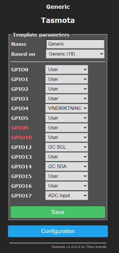
- GPIO 4 for the Ikea particulate sensor input
- GPIO 1 for FTDI TXD
- GPIO 3 for FTDI RXD
- GPIO 12 for I2C SCL
- GPIO 14 for I2C SDA
- ADC for LDR input
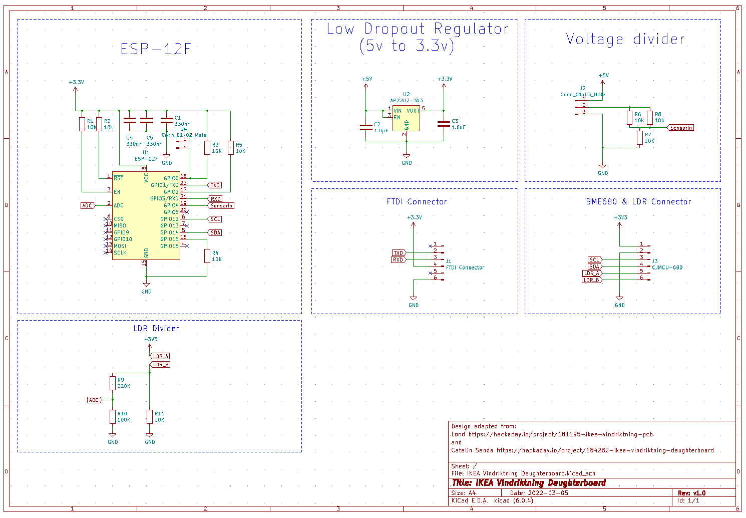
IKEA Vindriktning Daughterboard Schematic
A slight modification of Catalin Sanda's design on https://hackaday.io/project/184282-ikea-vindriktning-daughterboard which adds an input for a light dependent resistor into the ADC. I have also chosen to use different inputs. I also added the Molex picoblade sockets as suggested by Lond's project https://hackaday.io/project/181195-ikea-vindriktning-pcb. The looms were challenging to work with and took some time to get right. The Molex picoblade connectors look beautiful, but the crimps are tiny and practice makes perfect in getting them right. If I did this project from scratch again, I would purchase pre-crimped plugs and then terminate the tails. I bought a cheap crimp tool so I am sure the experience with the £200 ratcheted Molex crimp tool is far better, but it was too expensive for this project.
Modification of the IKEA Vindriktning PCB
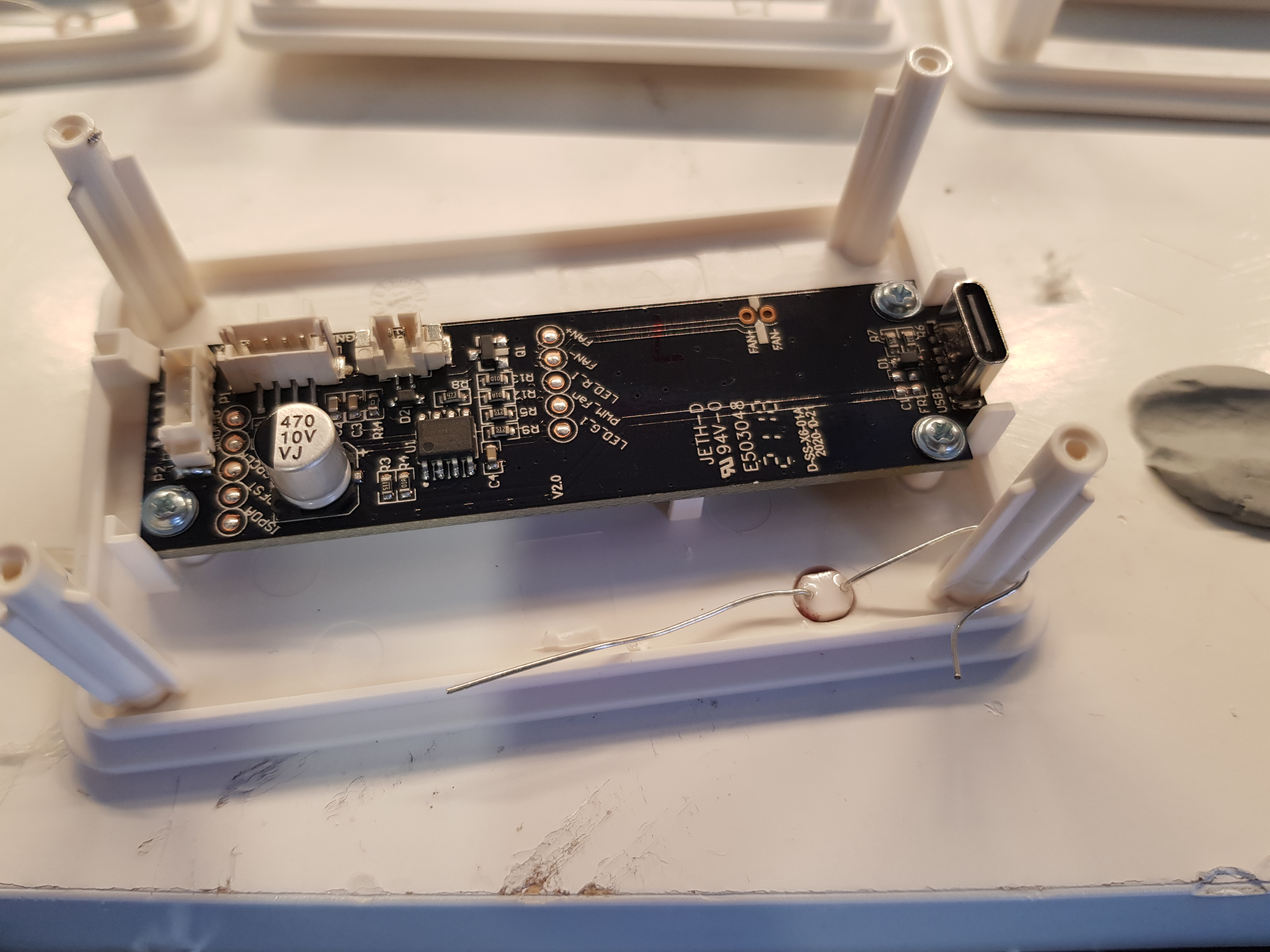
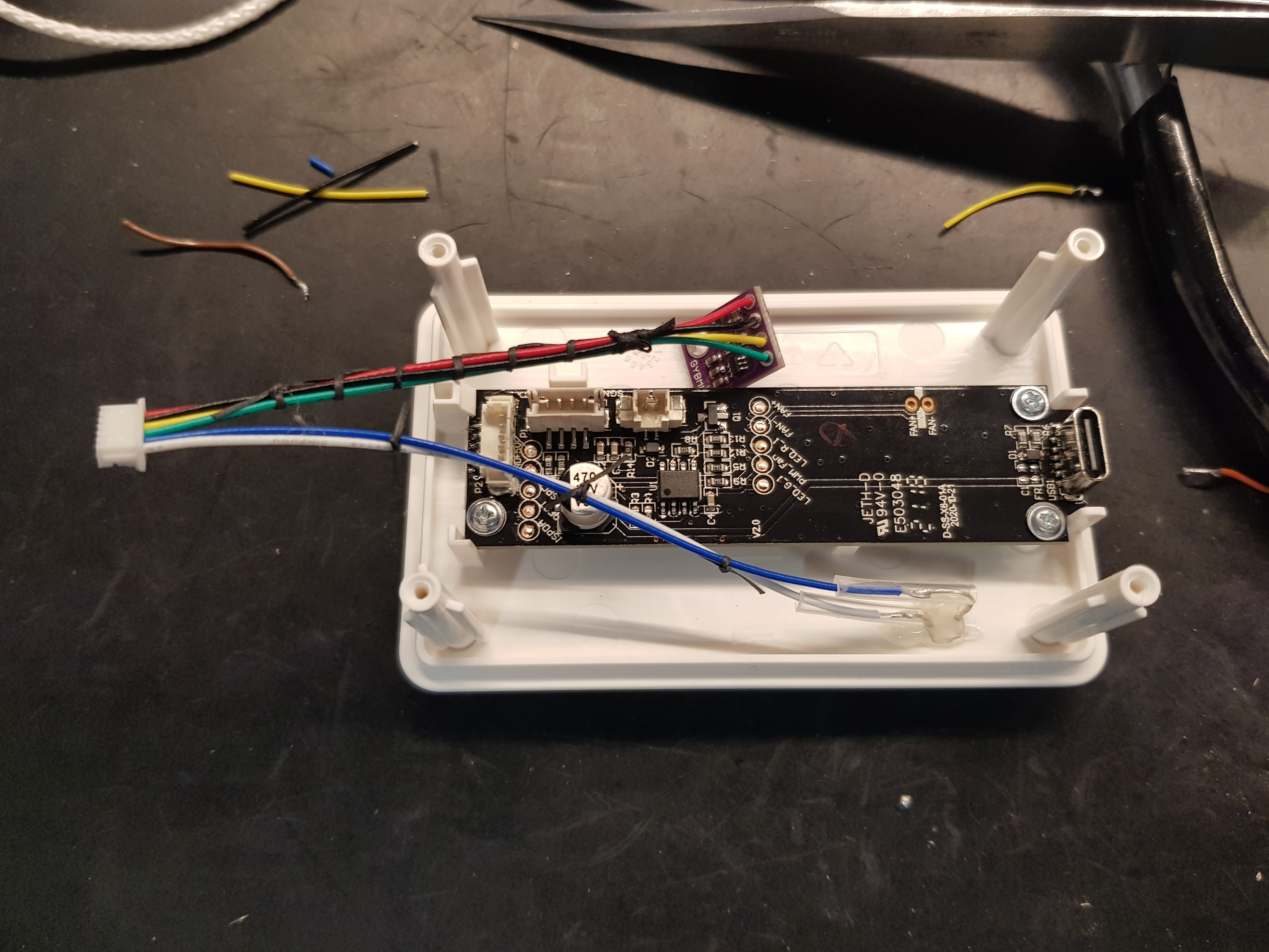
The designers were very generous in making the board accessible to makers. In order to use connect the daughterboard neatly, a 5 way Molex SMD socket should be soldered to the board (pictured on the LHS of the board). As others have done in their solutions, it is possible to solder directly to the board.
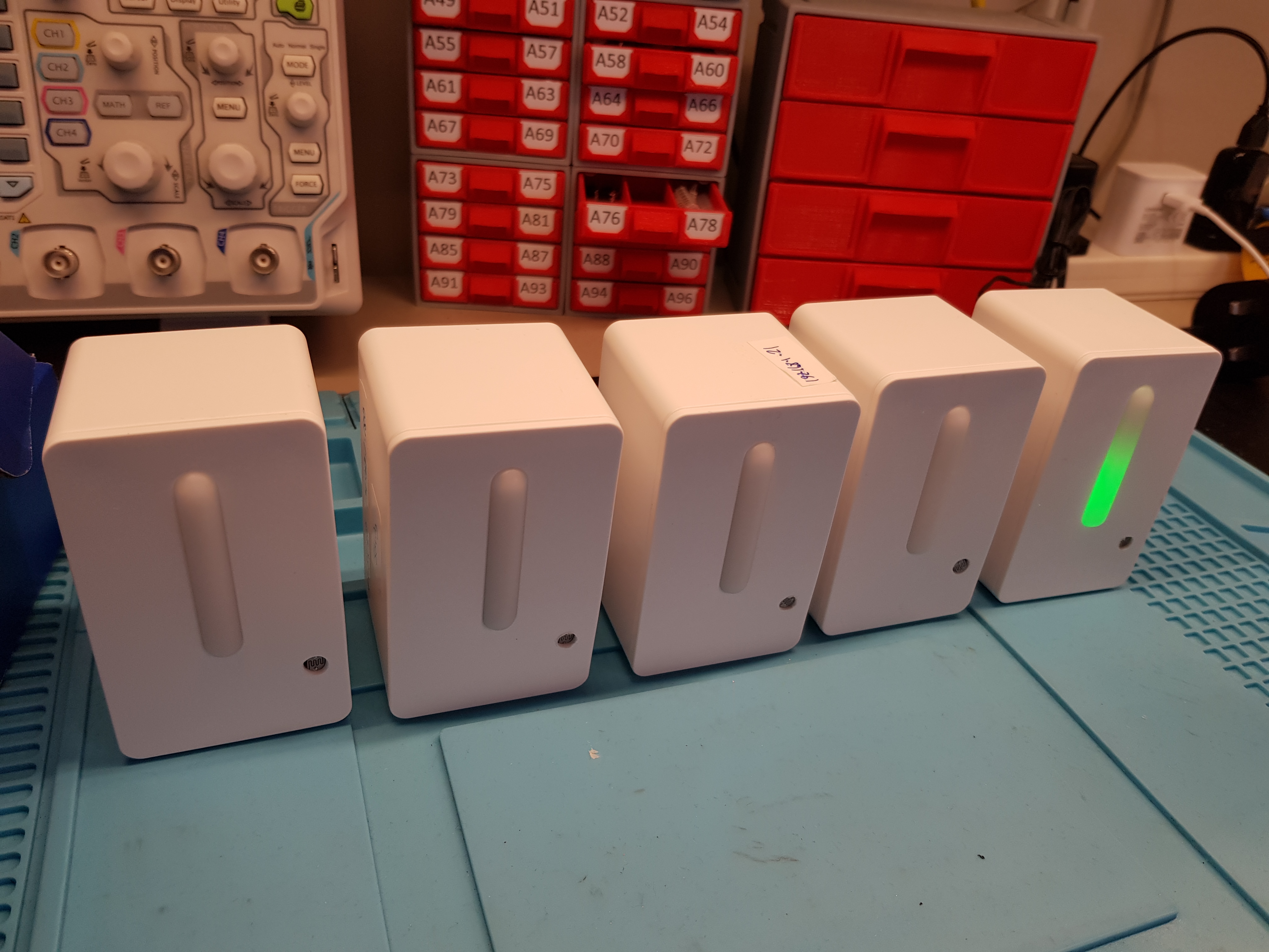
The light dependent resistor is fitted to the fascia as pictured and terminals insulated. I kept the BME280 loose to allow for placement away from the fascia in the other half of the enclosure.
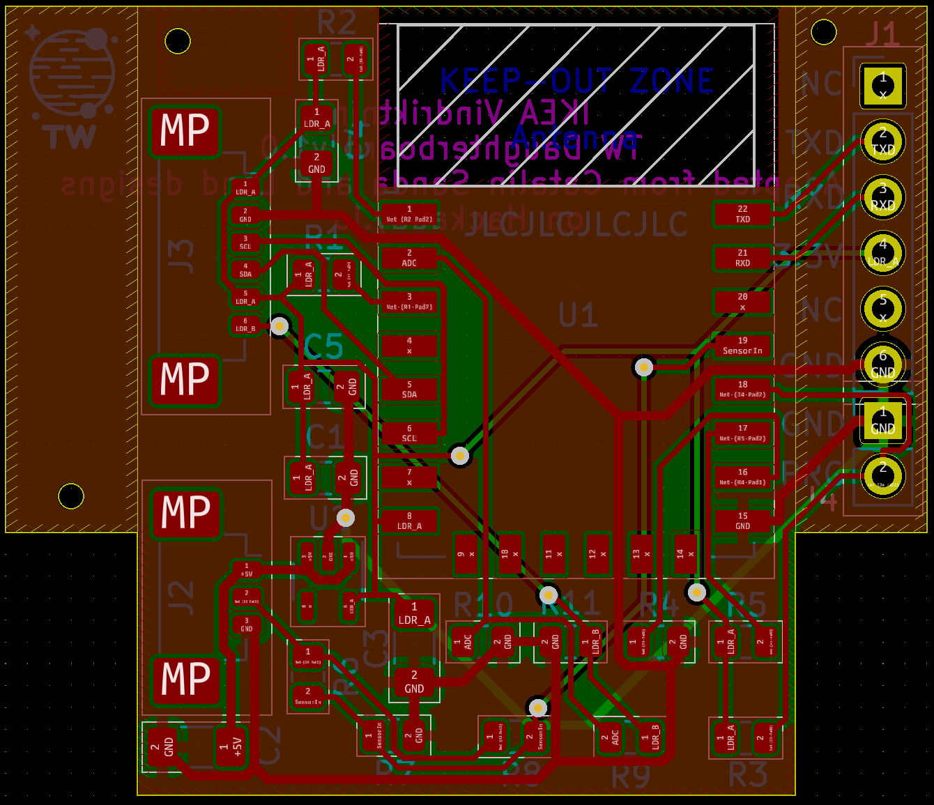
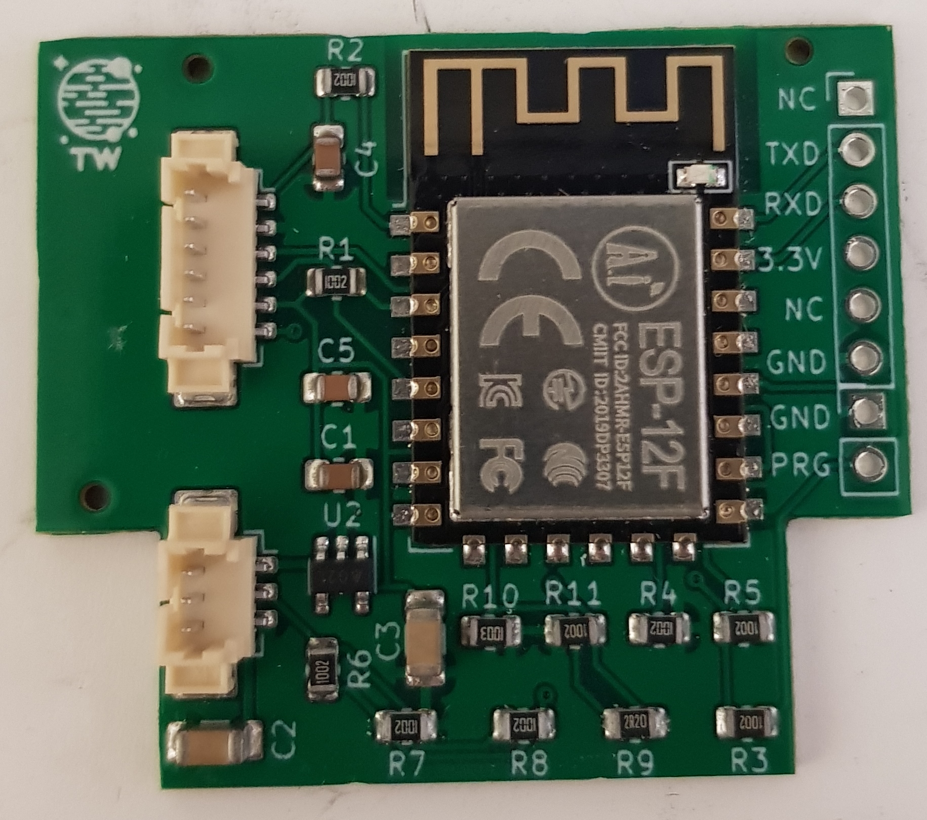
Daughterboard
Pictured as received from JLCPCB. Note R9 pictured reflects the BOM error which fitted a 2R2 resistor, rather than 220K0. The repo BOM has been corrected.
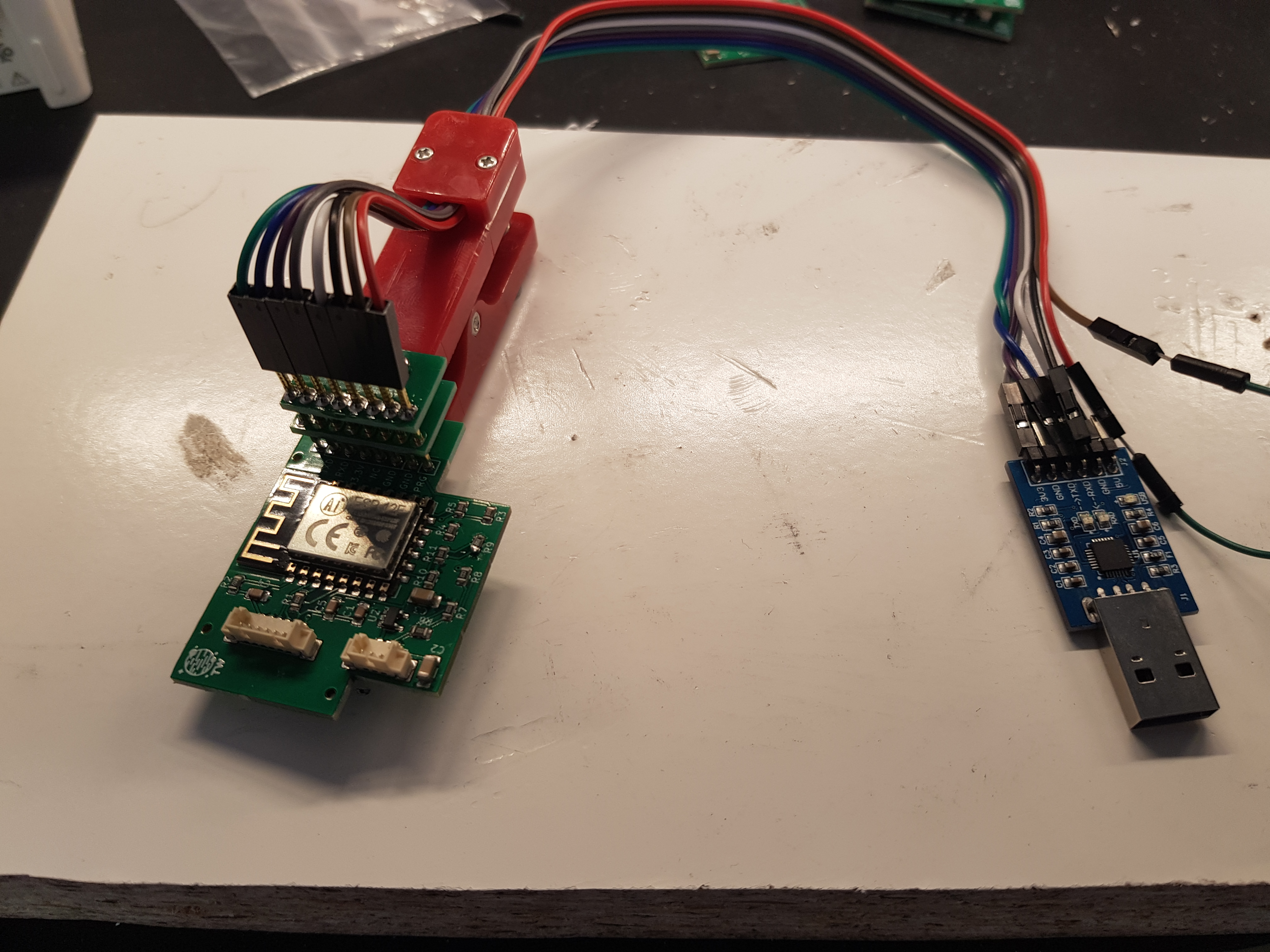
I copied the Caralin's flashing method and will use the same method in future boards. The PRG pin is shorted to ground away from the board. I bought mine from AliExpress which seems to work quite well LINK I flashed the boards with Tazmotizer with the version that contains the Vindriktning peripheral. Alternatively use tasmota-allsensors unoffical build although this is untested. The version I used is within this repo.
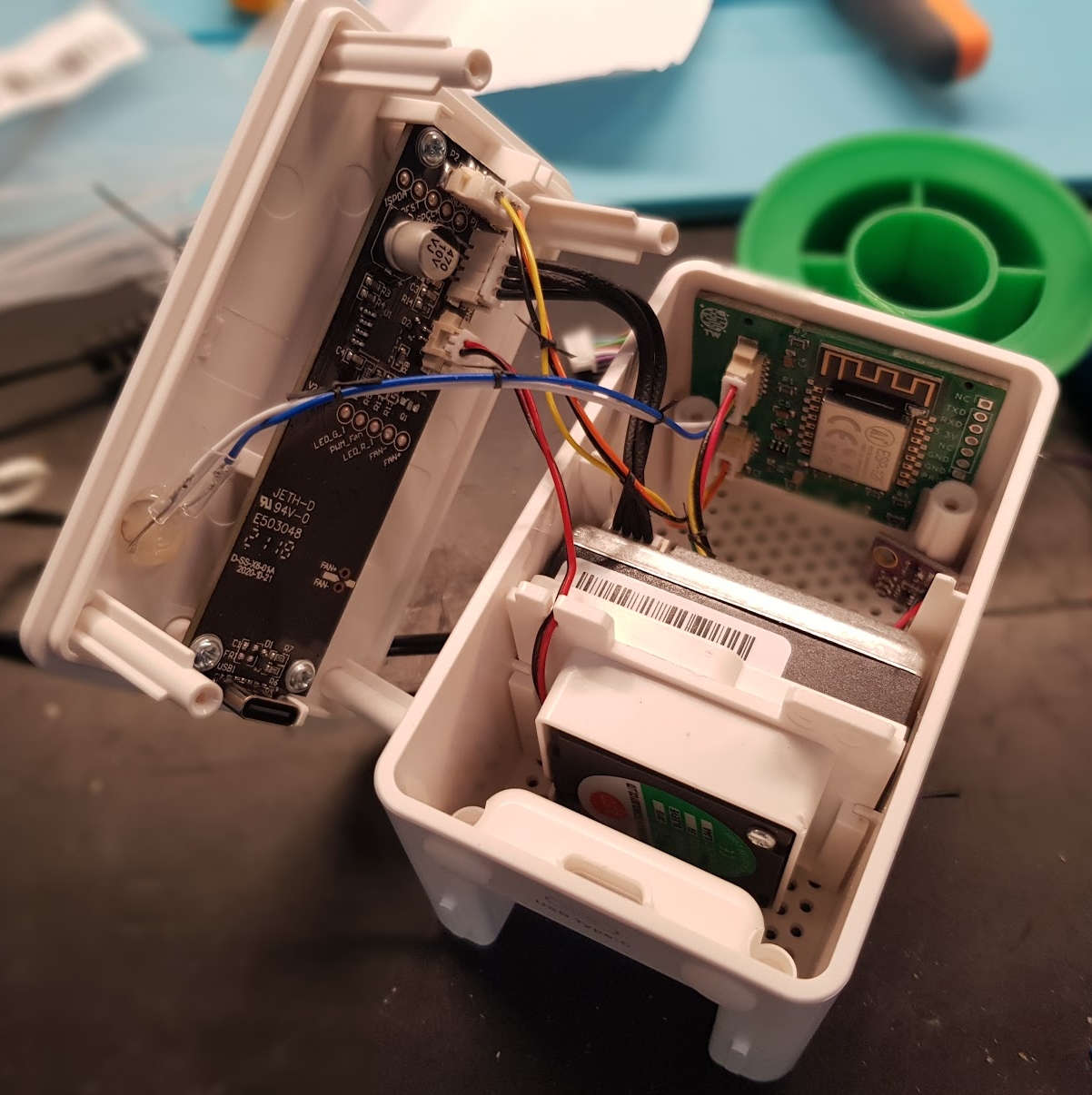
The spring in the laced BME280 loom positions the board out of the way. Once you have tested, you may wish to secure it. The board itself slides behind the screw pillars.
Tasmota Setup
Once fitted, configure the module as follows.
Which should generate a home page like this.
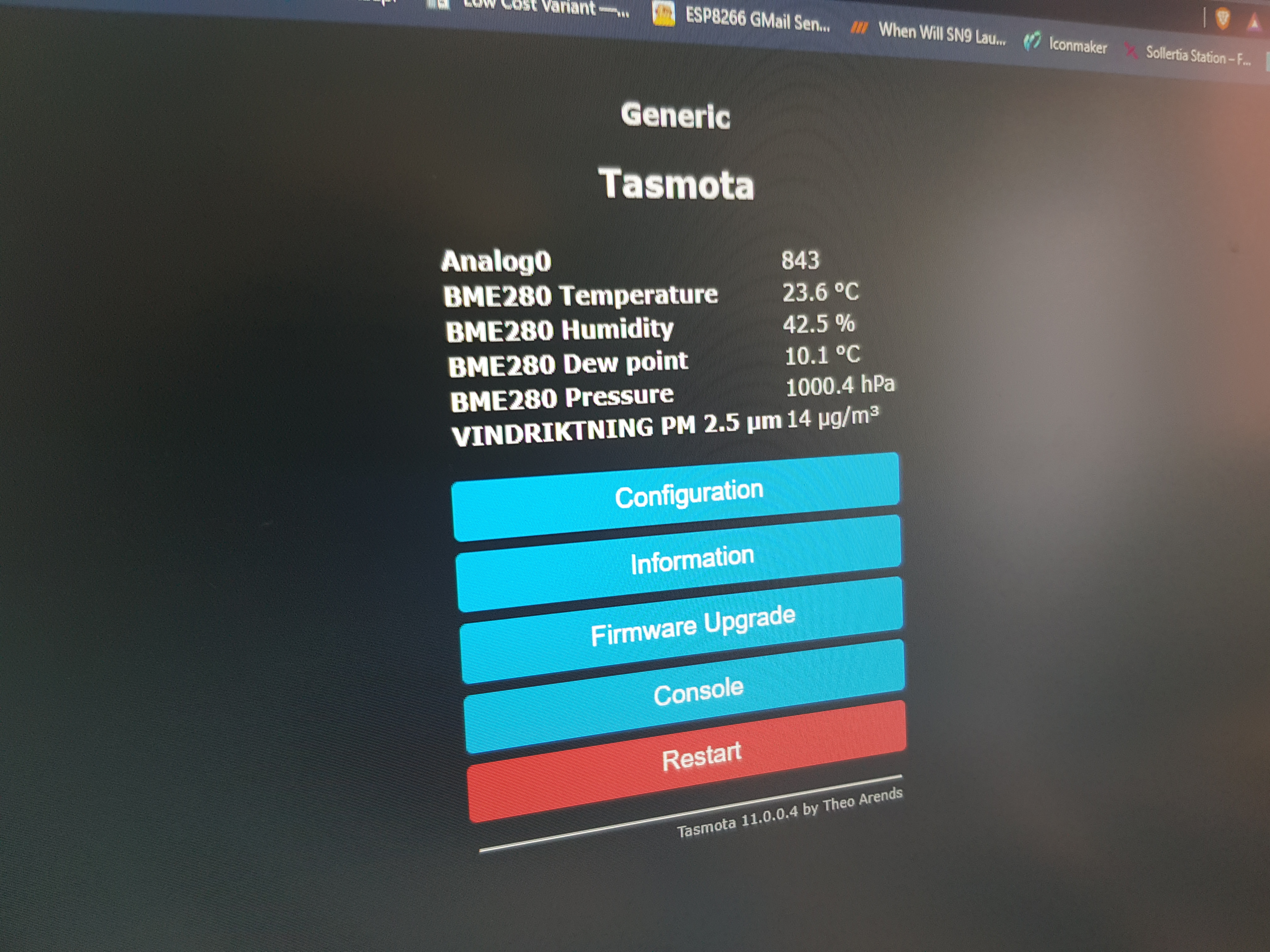
To change the device name, go to the "other options" page and set there.
In use
I use mine with my other house sensors signalled with MQTT. My MQTT setup uses Mosquitto and NODERED.
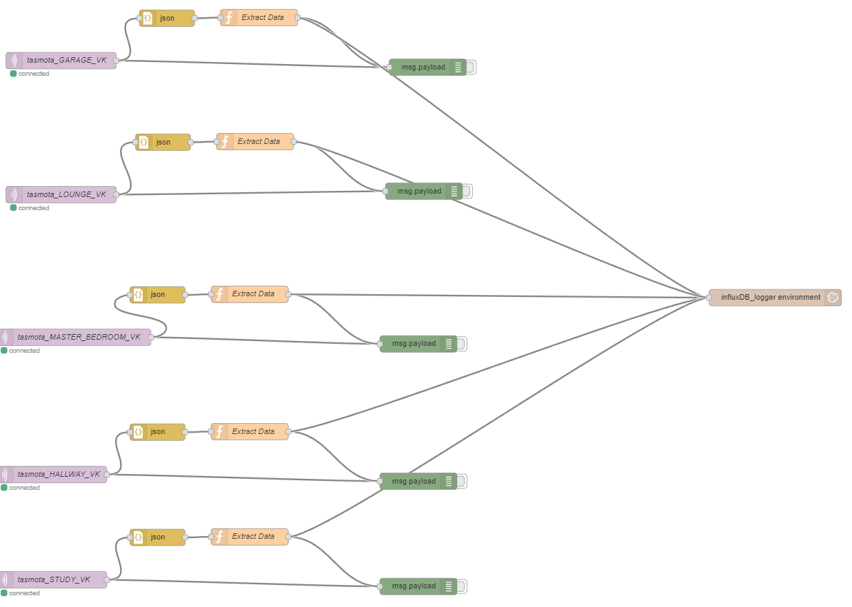
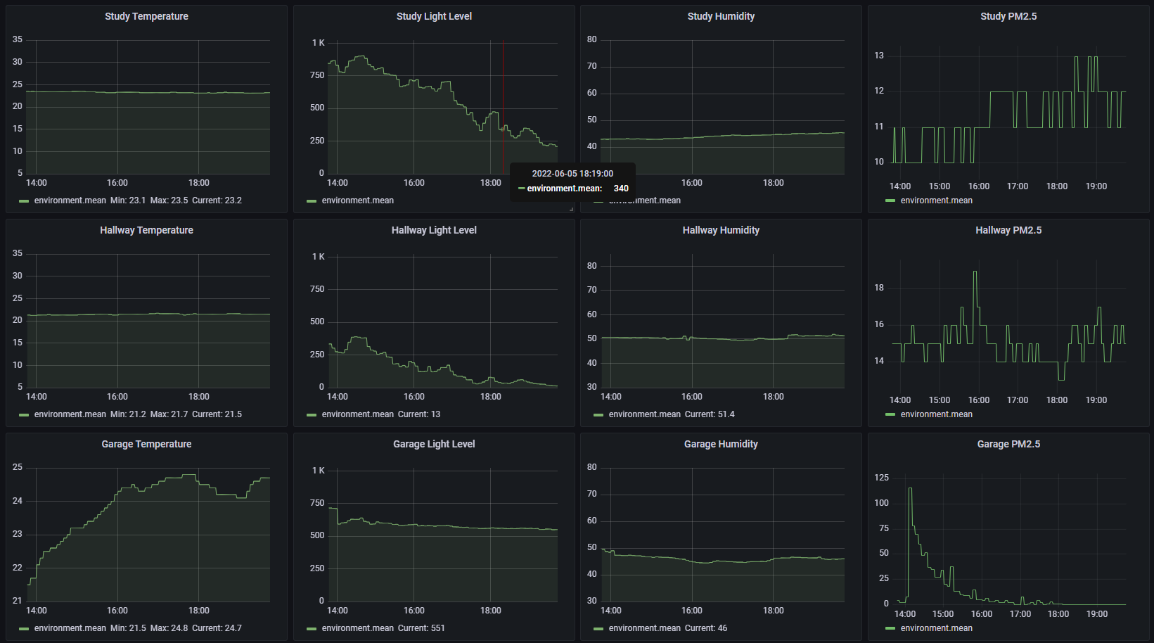
The data is stored in an InfluxDB 3.x database and viewed on Grafana. The garage peak is probably due to me sweeping up after completing this project!
How to order populated PCB with JLCPCB
Phil's Lab - Kicad design and JLCPCB Assembly for ordering this board.
- Go to JLCPCB and log in.
- Click on "Instant quote".
- Upload the zipped gerber.
- Review the board parameters (you may click remove order number if you wish).
- Click PCB assembly.
- Click Tooling Holes "Added by Cuastomer" and agree the T&C if you are happy with them.
- Click confirm.
- Click "Add BOM File", browse for IKEA_Vindriktning_Daughterboard-TW_bom.xls file in the assembly directory.
- Click "Add CPL", browse for IKEA_Vindriktning_Daughterboard-all-pos.xls file in the assembly directory.
- Select Sensor/Controller/Precision Instrument/Temperature sensor" or similar in the description combobox, probably for customs declarations.
- Check the matched part detail, especially the values and if they are in stock. You may have to search for alternative parts if there are none in stock. Check the footprints of alternatives.
- Click next.
- The review parts placement window will probably show incorrect rotation on some parts, this will be checked and corrected by JLCPCB.
- Save to cart and order.
Vindriktning Links
Catlalin Sanda Hackaday.io blog post
Lond's Hackaday.io blog post
Blakadder's IKEA Vindriktning air quality sensor running Tasmota
Hypfer/esp8266-vindriktning-particle-sensor
Vccground implementation - #34 VINDRIKTNING | Modifying to the next level as Standalone / Home Assistant Connected Multi Sensor includes a schematic of the Ikea board.
Other Links
Tasmota Home
tasmota-allsensors unoffical build
Phil's Lab - Kicad design and JLCPCB Assembly for ordering this board.
